Inter-VLAN Routing (IVR): The Complete Guide
Inter-VLAN Routing (IVR) is the process of forwarding network traffic between hosts residing in different Virtual Local Area Networks (VLANs) using a Layer 3 routing engine.
By default, VLANs isolate traffic at Layer 2 to segment broadcast domains and provide security. Devices in different VLANs cannot communicate directly at Layer 2—even if they are plugged into the exact same physical switch. To enable controlled communication between departments, packets must cross a Layer 3 gateway.
The 3 Methods of Inter-VLAN Routing
| Method | Physical Connectivity | Gateway Location | Scalability |
|---|---|---|---|
| Legacy Routing | 1 physical cable per VLAN | Physical Router Interfaces | Very Poor (Runs out of physical ports quickly) |
| Router-on-a-Stick (ROAS) | 1 physical cable (802.1Q Trunk) | Router Sub-interfaces (e.g., G0/0/0.10) | Moderate (Limited by trunk link bandwidth) |
| Multilayer Switching (SVI) | Internal switch backplane | Switched Virtual Interfaces (interface vlan) | Enterprise Standard (Wire-speed ASIC hardware routing) |
1. Router-on-a-Stick (ROAS) Architecture
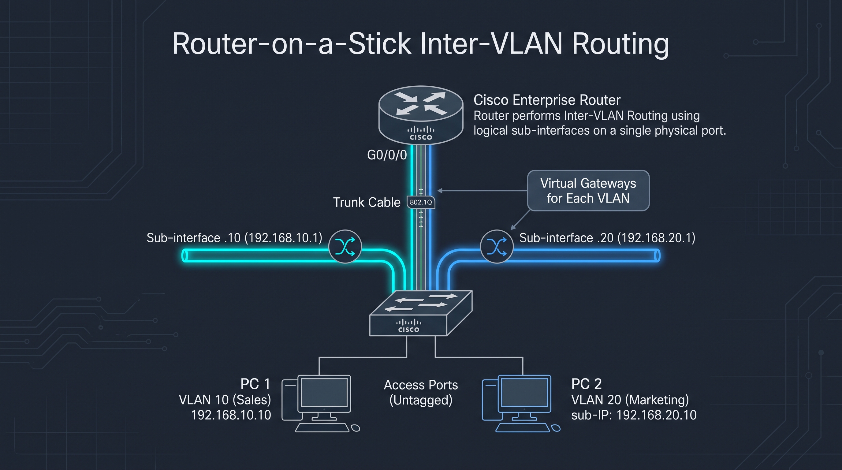
Router-on-a-Stick connects an external router to a Layer 2 switch over a single physical Ethernet interface configured as an 802.1Q trunk. The router divides that physical port into virtual sub-interfaces, where each sub-interface serves as the default gateway for a specific VLAN.
                    +-------------------+
                    |   Cisco Router    |
                    |   [ G0/0/0 ]      |
                    +---------+---------+
                              |  Single Physical Link
                              |  (802.1Q Trunk)
                              |
           .10 Gateway <------+------> .20 Gateway
      (192.168.10.1)                  (192.168.20.1)
                              |
                    +---------+---------+
                    |   Layer 2 Switch  |
                    |   [ Gig 0/1 ]     |
                    +----+-----------+--+
                         |           |
          [ Fa0/1 ] (Access)       [ Fa0/2 ] (Access)
                         |           |
                      [ PC 1 ]    [ PC 2 ]
                      VLAN 10     VLAN 20
                   (Sales Host)  (Marketing Host)
Router Configuration Commands (ROAS)
! 1. Bring up physical interface without assigning an IP Router(config)# interface gigabitethernet 0/0/0 Router(config-if)# no shutdown Router(config-if)# exit! 2. Sub-interface for VLAN 10 Router(config)# interface gigabitethernet 0/0/0.10 Router(config-subif)# encapsulation dot1Q 10 Router(config-subif)# ip address 192.168.10.1 255.255.255.0 Router(config-subif)# exit
! 3. Sub-interface for VLAN 20 Router(config)# interface gigabitethernet 0/0/0.20 Router(config-subif)# encapsulation dot1Q 20 Router(config-subif)# ip address 192.168.20.1 255.255.255.0 Router(config-subif)# exit
2. Multilayer Switching (SVIs)
In modern enterprise networks, an external router introduces a traffic bottleneck. Layer 3 switches perform Inter-VLAN routing internally at wire speed using Switched Virtual Interfaces (SVIs).
Crucial Multilayer Switch Rule
By default, Layer 3 forwarding is disabled on Cisco Catalyst switches. You must run ip routing in global configuration mode, or packets will not cross between VLANs!
Multilayer Switch SVI Configuration
L3-Switch(config)# ip routing! Default Gateway for VLAN 10 L3-Switch(config)# interface vlan 10 L3-Switch(config-if)# ip address 192.168.10.1 255.255.255.0 L3-Switch(config-if)# no shutdown L3-Switch(config-if)# exit
! Default Gateway for VLAN 20 L3-Switch(config)# interface vlan 20 L3-Switch(config-if)# ip address 192.168.20.1 255.255.255.0 L3-Switch(config-if)# no shutdown L3-Switch(config-if)# exit
Verification Commands
show ip interface brief— Verifies that sub-interfaces or SVIs are in anup / upstate.show ip route— Confirms directly connected subnets appear in the routing table (marked withC).show interfaces trunk— Verifies that the uplink port carries 802.1Q tagged frames between switch and router.
Direct Link: https://tucvqsutvgwenpzyzdrc.supabase.co/storage/v1/object/public/labs/x1k4siskfur_IVR.pkt
🛠️ Hands-On Cisco Packet Tracer Lab Files
Put theory into practice by testing this exact topology in Cisco Packet Tracer. Download the pre-built .pkt lab file and the complete step-by-step CLI configuration guide below: