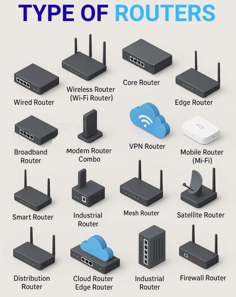
Networking Devices (Part 2): The Enterprise Network Router
A Network Router is an intelligent internetworking device that operates primarily at Layer 3 (Network Layer) of the OSI model. While a Layer 2 switch connects endpoints inside a local broadcast domain, a router connects distinct, independent networks together (such as interconnecting different corporate subnets, branch offices, or routing LAN traffic out to the public Internet).
Without routers, global data communication would collapse under the weight of broadcast traffic. Every interface on a router represents an isolated Layer 3 network, meaning routers inherently terminate and break broadcast domains.
1. Layer 2 Switch vs. Layer 3 Router
Understanding the fundamental architectural boundary between switching and routing is essential for any network engineer:
| Operational Feature | Network Switch (Layer 2) | Network Router (Layer 3) | | :--- | :--- | :--- | | Primary OSI Layer | Layer 2 (Data Link) | Layer 3 (Network) | | Addressing Evaluated | 48-bit Physical MAC Addresses | 32-bit (IPv4) or 128-bit (IPv6) Logical IP Addresses | | Forwarding Database | CAM / MAC Address Table | Routing Table (RIB) & Forwarding Table (FIB) | | Broadcast Domain Boundary | Maintains 1 broadcast domain across all ports (unless split by VLANs) | Every single interface defines a separate, isolated broadcast domain | | Header Modification | Preserves original Layer 2 frame intact | Strips incoming Layer 2 header, decrements TTL, rewrites new Layer 2 framing | | Primary Purpose | Connects end hosts within the same local network | Routes data packets between different IP subnets and external networks |
2. Inside the Router: Control Plane vs. Data Plane
An enterprise router operates two decoupled processing planes:
- Control Plane: The intellectual engine running on the CPU. It handles routing protocols (such as OSPF, EIGRP, and BGP), processes neighbor hellos, computes optimal paths, and builds the Routing Information Base (RIB).
- Data Plane (Forwarding Plane): The high-speed transit pipeline powered by specialized hardware (ASICs). It receives incoming packets, checks the Forwarding Information Base (FIB) and Adjacency Table via Cisco Express Forwarding (CEF), swaps Layer 2 headers, decrements the IP Time-to-Live (TTL) field, and pushes packets out the egress port at wire speed.
3. The Routing Decision Logic (Longest Prefix Match)
When a router receives an IP packet, it consults its Routing Table to determine the next-hop interface using strict precedence rules:
- Longest Prefix Match (LPM): The router chooses the route with the most specific subnet mask (e.g.,
10.1.1.0/24beats10.0.0.0/8regardless of routing protocol). - Administrative Distance (AD): If two routing sources learn identical subnets with the exact same prefix length, the router installs the path with the lowest administrative distance (Directly Connected:
0, Static:1, eBGP:20, OSPF:110, RIP:120). - Metric: If the protocol and prefix match, the router uses the route with the lowest metric (e.g., OSPF cost based on interface bandwidth).
4. Routed Inter-Subnet Topology Diagram
+---------------------------------------------------------------------------------+
| Cisco ISR Router |
| |
| [ Gig 0/0/0 ] [ Gig 0/0/1 ] |
| 192.168.10.1/24 192.168.20.1/24 |
+--------------------+-----------------------------------------------+------------+
| |
v v
+-------------------+ +-------------------+
| Switch A (LAN) | | Switch B (LAN) |
+---------+---------+ +---------+---------+
| |
v v
[ PC 1 ] [ PC 2 ]
192.168.10.10 192.168.20.10
Default GW: 192.168.10.1 Default GW: 192.168.20.1
===================================================================================
ROUTER ROUTING TABLE (show ip route)
===================================================================================
C 192.168.10.0/24 is directly connected, GigabitEthernet0/0/0
C 192.168.20.0/24 is directly connected, GigabitEthernet0/0/1
